| Well streams are complex mixture of hydrocarbon gases and oils, frequently contaminated extras of water and solids .I.e sand. A separator is used to split up the various fractions which then proceed to further treatment as necessary.
Separators can be two phases, to separate gas from liquid or three phases, to separate gas , oil and water. Sand cleaning facilities can be incorporated to separators handling well streams with sand, in principle a separator is a vessel in which oil, gas and water and sand can be separated by gravity. In practice a separator contain internal which increases the efficiency of separation process.
LAKSEL Oil and Gas Division engineers select the best combination of separator feature for each application. All product manufactured confirm to the code and standards of Asian, American, European and Scandinavian countries.
SEPARATOR TYPE
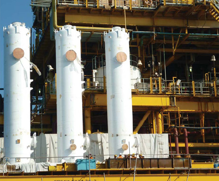
| Vertical |
|
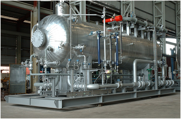
Horizontal |
| |
|
|
- Good space saving design where installation area is limited.
- Good surge handling characteristics.
- Good tolerance of large liquid level rises due to surges.
- Good bottom drain and clean out features of particular advantage when well streams contain large quantities of mud and sand.
|
|
- More economical design for larger oil rate.
- More economical for handling larger volumes of gas.
- Better foam handling characteristics.
- Easily skid mounted and fitted with accessories ready for installation.
|
Separator Sizing
LAKSEL EPS Technologies Pte Ltd Oil and Gas Division have available a team of engineers who specialize in oil and gas production equipment and who can determine the ideal size of separator and best choice of separator internal for each application.
Every case is given individual treatment and purpose designed for the specific application .We do not believe in providing a catalogue of standard separator and selecting the nearest and making do ‘ .Every separation duty has its own unique set of requirements and so it is our policy to individually engineer every separator according to its requirement. The Oil and Gas Division of Laksel have design engineers available to determine the best design for every application. Just let us know our requirements and will find the answers.
The stages of separation
Initial separation
Well stream fluid enters the separator under pressure into an unrestricted space. The first stage of separator is to slow the jet of well stream fluid using an inlet diverter. When the fluid hit the diverter, the stream is broken up, allowing the gas to break out immediately. Oil fails to the bottom of the separators from where it flows to the downstream m of handling system, whilst gas being lighter ,rises to the top and goes from there in to the gas gathering system.
Flow smoothing
Turbulence of the liquid surface will prevent gravity separation and may even cause re-entertainment .Smoothing of the flow pays dividends in allowing the nature forces of gravity separation to proceed unimpeded and applies particularly to application using horizontal separations, where the liquid surface is relatively large.
Demisting
Whilst the vast majority of liquid is separated with the inlet diverter, small droplets remain in the gas stream as a mist. Mist is separated in two stages , gravity separation to eliminate the larger particles which represent the major fraction ,following by a mist extractor to remove the final traces.
The use of baffles
For most application using horizontal separators, one or more of the following problem arises.
- The gas rate is too high so that droplet would be swept along the length of the vessel before having time to fall to the liquid surface.
- The vessel diameter is large so the droplet have to far to fall to the liquid surface in the time taken for the droplet to travel along the separator.
The use of baffles overcomes the problem just described .Firstly they act as a straightening vanes and smooth out the turbulent flow, allowing the liquid droplet to fall. Also they reduce the distance the droplet has to fall before it coalesces with the film of liquid on the plate. This film of liquid drains down into the main bulk of separated liquid
Defoaming baffles
A specific gas/oil separation problem is foam. Baffles prove a very effective solution. More section of baffles are required as foaming is a more severe problem than for demisting alone. Many types of defoaming internals have been tested over the years but many, whilst breaking foam create turbulence which whips up more foam. LAKSEL Baffle design smooth out the gas flow and provide a large surface area into which the foam can coalesce and drain into the main stream
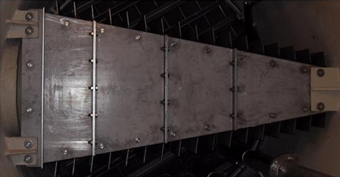
Sand Jet system
To prevent solids accumulation within the bottom of the vessel a sand jetting system is provided as shown in the picture below. The jetting system comprises horizontal header pipes into which both jetting and flushing nozzles are installed. Above the sand drains runs a sand pan that prevents the clogging of the sand drain nozzles prior to flushing. This is especially important for on-line flushing since it is very difficult to clean a blocked nozzle.
Difference Between Vertical & Horizontal Separators
In vertical separator the inlet is arranged to make the gas flow in a cyclonic fashion which through the heavier liquid droplet outwards under centrifugal action onto the wall of the vessel to then drain down into the main bulk of separated oil . The remaining the mist droplet is removed by the mist extractor.
With horizontal separator the flow of gas is itself horizontal along the length of the vessel, so that the particle of liquid can fall towards the liquid surface as it travel along the length of the vessel. If the separator size (determined by liquid handling capacity)is sufficiently large so that the larger droplet can fall to the liquid surface within the length of the vessel. then a mist extractor to remove the last surface of fine droplet is all that is required.
Construction
All units can be manufactured to comply with recognized code and standards.
Skid mounted units designed by our engineers significantly simply transportation and installation on site. Either onshore or offshore, in all cases instruments, control , valves and hook-up of all electrical and pipe work can be included as part of the skid mounted package . Hup Seng Offshore Engineering Systems’ separation equipments complements an extensive range of process equipment , which include filters ,coalescers, and gas dehydration. |